

Reducing the Cost of Direction Finding: Building a Reproducible RF Calibration Platform
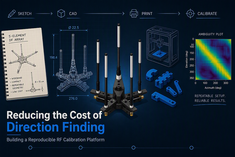
Direction Finding (DF) allows us to determine which direction a radio frequency (RF) signal is coming from by comparing how that signal arrives at multiple antennas. Achieving accurate direction estimates requires more than sophisticated algorithms and receivers; it also depends on maintaining a precisely known antenna geometry and a repeatable calibration process. By designing a modular five-element antenna array using commercially available RF hardware, 3D-printed components, and a low-cost calibration platform, we created a reproducible system that makes DF experimentation more accessible while preserving the consistency needed for meaningful RF measurements. By the end of this blog, you will understand how antenna array design, mechanical repeatability, and calibration influence DF performance, and how you can build and validate a low-cost DF platform of your own for experimentation and learning.
The following blog post is from work performed during Spectric’s Summer Intern Program. For more information on our Intern Program please reach out to info@spectric.com.
#DirectionFinding #RF #SDR #KrakenSDR #AntennaArray #3DPrinting #SignalGeolocation #SpectrumOperations #Engineering #SpectricLabs
Making Direction Finding Accessible
Direction Finding, or DF, determines the direction of arrival of a radio frequency signal by comparing how that signal appears across multiple antennas. Discussions of DF often move quickly to algorithms, receivers, and signal processing. Those pieces matter, but they depend on a more practical foundation: a physical system that can be built, moved, calibrated [see our previous blog post on how we calibrated the KrakenRF Direction Finding Array ], and tested repeatably.
As part of Spectric’s Summer Intern Program, we set out to explore an engineering question: can we build a low-cost, reproducible platform that allows engineers, students, and RF hobbyists to experiment with direction finding without relying on expensive custom hardware or specialized manufacturing equipment?
The result was a lightweight, modular, five-element antenna array designed around commercially available RF hardware, 3D-printed components, and a repeatable calibration workflow. The goal was to solve a practical problem: create an accessible platform that makes DF experimentation easier to build, calibrate, transport, and improve.

Why Repeatability Matters
Direction-finding systems estimate the angle of arrival of an RF signal by comparing phase and amplitude differences across antennas. That means physical consistency matters. If antenna placement shifts between tests, cable routing changes, or the array geometry moves during assembly or transport, the measurements no longer match the calibration data. Small mechanical changes can become real errors in the direction estimate.
That was the core challenge behind this project, was not simply attaching antennas to a structure. The key was designing a structure that could hold those antennas in consistent positions, support repeatable cable routing, survive repeated use, and remain easy enough for others to reproduce.
For a low-cost DF platform, repeatability is what makes the system useful. It gives engineers a stable baseline for calibration, testing, and comparison. Without that stable baseline, it becomes difficult to tell whether a change in performance came from the algorithm, the antenna spacing, the cable layout, the material, or the test setup itself.
Designing a Low-Cost Array
The array was designed for a KrakenSDR-based direction-finding system and uses five antennas, which gave the team a practical balance between DF capability, mechanical complexity, and system constraints. The design also supports both 10 cm and 15 cm radius configurations, allowing different array geometries to be evaluated without creating an entirely new structure.
Instead of using a solid circular plate or machined structure, the team developed a modular wing-and-body architecture. Each antenna mounts to an individual wing that attaches to a central hub. This reduced weight and material usage while preserving the rigidity needed for repeatable antenna placement. It also allowed individual sections to be replaced, modified, or reprinted without rebuilding the entire array.

Cost was a major design consideration. Rather than relying on custom-machined parts, the team used commercially available RF hardware and custom 3D-printed components. That kept the design accessible and made it possible to manufacture the array using common desktop printers.
The modular approach also made the platform more useful as a learning and experimentation tool. Engineers can modify a section, test a different material, adjust spacing, or experiment with a new configuration without starting from scratch. For an RF experimentation platform, that flexibility is valuable because the design is not locked into a single use case or one fixed geometry.
Material Selection and Manufacturing
Because mechanical stability directly affects DF repeatability, material selection became more than a manufacturing decision. The team evaluated common 3D-printing materials and the tradeoffs each introduced. PLA is easy to print, but it can deform under elevated temperatures. More flexible materials may improve impact resistance, but they can also introduce unwanted movement into the antenna structure.
For the final design, the team selected ABS because it provided a useful combination of rigidity, durability, and improved temperature resistance. Those characteristics helped the array maintain consistent geometry during transport, calibration, and outdoor testing.
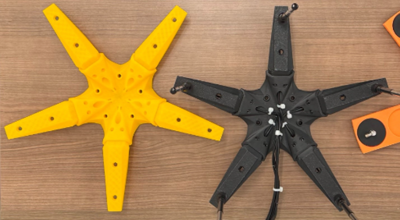
The manufacturing process was intentionally iterative. Before committing to full-size prints, the team produced smaller test sections to validate antenna mounts, fitment, and structural interfaces. That helped identify tolerance issues early and allowed the design to be refined before producing final components.
That process reinforced a key RF engineering lesson: small mechanical details can have a meaningful impact on system performance. Mounting methods, cable routing, material behavior, connector strain, and manufacturing tolerances all influence whether a DF system can be calibrated and trusted.
Building for Calibration
The antenna array was only one part of the effort. Reliable DF testing also requires a calibration setup that can be repeated consistently. To support that need, the team developed a low-cost calibration rig that helps maintain array geometry and test setup consistency across experiments.

The calibration platform was designed to support learning and experimentation rather than chase a single absolute performance number. By keeping the test setup repeatable, the team could more clearly evaluate changes to antenna spacing, materials, cable routing, frequencies, or processing approaches. That makes the platform useful as an engineering tool, not just as a one-time build.
This is where low cost and technical value come together. A reproducible platform makes DF more approachable, but it also improves the quality of experimentation. When the physical setup is stable, changes in results are easier to interpret. That gives engineers a better foundation for understanding what is actually affecting performance.
Assembly and System Integration
The final assembly used identical antennas, equal-length phase-matched coaxial cables, and consistent mounting hardware across all five channels. Maintaining channel-to-channel consistency is critical because DF algorithms rely on accurate phase relationships between received signals. Even small hardware differences can introduce errors that affect direction estimates.
Cable management was also built into the mechanical design. Dedicated routing paths helped reduce connector strain and limit cable movement during use, both of which support more repeatable measurements.
The completed array provided a clean, portable, and reproducible platform for calibration, testing, and future DF experimentation. It also demonstrated one of the most important lessons from the project: successful RF systems are shaped by practical engineering decisions as much as by software or signal processing.
Making the Work Reusable
A major goal of this project was accessibility. The platform was designed so that others could reproduce it, modify it, and build on it using commonly available hardware and consumer 3D printers.
To support that goal, Spectric has made key project artifacts available, including 3D-printable STL files and CAD models available on our Github. These resources will give readers a natural next step beyond the blog post: download the files, build the array, examine the code, and adapt the design for their own DF experiments.
This open, reproducible approach is important because it turns the project into more than a summary of work already completed. It becomes a starting point for other engineers who want to explore DF concepts, test low-cost RF hardware, or understand how mechanical design choices affect RF measurements.
Conclusion
This project started with a practical question: how do we make direction-finding experimentation more accessible without losing the repeatability needed for meaningful RF testing?
By combining commercially available RF hardware, custom 3D-printed components, a modular five-element antenna array, and a low-cost calibration rig, the team created a platform that supports learning, testing, and continued development. The work highlighted the connection between mechanical design and RF performance, while showing that useful DF experimentation does not have to depend on expensive custom hardware.
For Spectric, this is exactly the kind of project we want to share through the blog: real engineering work, practical technical depth, and a clear look at how our team approaches complex RF problems. It gives candidates a view into the kinds of problems our engineers work on, gives partners and customers a concrete example of our RF and system-integration thinking, and creates reusable material that can support future technical conversations.
Build It Yourself
Interested in building or modifying the array? You can find the STL files and CAD assets here: https://github.com/spectriclabs/direction_finding_array/, so others can reproduce the design and adapt it for their own direction-finding experiments.
For more information about Spectric’s internship program, contact info@spectric.com.
Spectric Labs Github: https://github.com/spectriclabs
For more information/questions contact info@spectric.com

Comments