

Calibrating the KrakenRF Direction-Finding Array: Signal Geolocation with Proper SDR Calibration

Direction Finding (DF) is the art and science of determining where a signal is coming from, using nothing more than an array of antennas carefully arranged and calibrated. DF is achieved by arranging a set of antennas in a specific, known geometric pattern. As a radio wave propagates through space, it reaches each antenna at slightly different times, creating measurable phase differences between the antennas. By carefully analyzing these phase delays, engineers can determine the direction from which the signal is arriving.
The following blog post is from work performed during Spectric’s Summer Intern Program. For more information on our Intern Program please reach out to info@spectric.com.
KrakenSDR
Software-Defined Radios (SDRs) such as the KrakenSDR leverage this principle by detecting and processing the phase differences across their antenna channels. Using precise measurements, these devices estimate the angle or bearing of the incoming radio signal, enabling accurate geolocation and signal tracking.
By integrating the directional data from several arrays, the system can triangulate the point where the bearings converge, effectively pinpointing the location of the transmission source. This capability is invaluable for applications such as radio signal monitoring, search and rescue operations, and spectrum management, as it enables precise localization even in complex environments. Accurate calibration of the antenna arrays ensures reliable measurements, facilitating robust direction finding and expanding the potential use cases of the KrakenSDR technology.

The Importance of Calibration in Precise Direction Finding
Achieving accurate direction finding (DF) with the KrakenSDR relies fundamentally on thorough calibration. Determining the direction of incoming signals depends on the KrakenSDR’s ability to understand the relationships among its antennas. Performing proper calibration allows the KrakenSDR to interpret signals correctly by accounting for a variety of critical variables
Variables Addressed by Calibration
Impedance, phase, and gain differences: Each antenna has unique electrical characteristics that can affect the signal.
Physical disparities: Variations in cable lengths and connector types may introduce timing and signal inconsistencies.
Processing delays: Delays between individual RTL-SDR chips within the KrakenSDR can impact synchronization.
Array geometry: The physical arrangement of antennas influences how signals are received and interpreted.
Environmental influences: Factors such as temperature, humidity, and the presence of nearby structures can affect measurements.
Signal frequency: The specific frequency being tracked can change how variables affect the system’s accuracy.
Even the smallest discrepancies, such as a nanosecond delay caused by a 6-inch cable difference, can result in location errors, sometimes off by several meters. Calibration compensates for these factors, ensuring that the KrakenSDR identifies the accurate location of a signal source.
Calibration Process
During calibration, a known signal is sent toward an antenna array from across the full range of incident degrees of azimuth and records the measurement to the receiver at each increment.
To calibrate the KrakenSDR:
A signal generator sends out a tone at a known frequency.
The direction-finding array records the phase difference at its current angle.
A manifold vector, a mathematical representation of the phase and amplitude relationships between antennas, is created for that frequency and angle.
Then the array rotates by 1°, repeating the process, until it completes a full 360° sweep.
To automate the calibration process and enable a 1° resolution for DF, an automated rotator platform moves each antenna to remove human interaction. [Look for a future Blog Post for our Automated Rotator Platform]

Debugging Calibration: The Ambiguity Plot
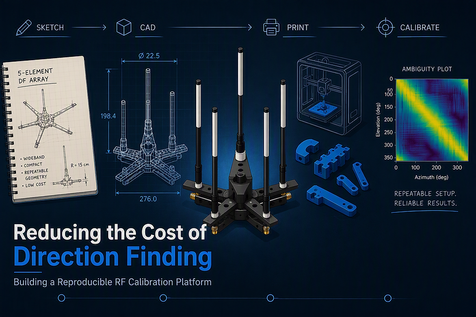
To ensure the calibration is accurate, the ambiguity plot is used. An ambiguity plot is a visual tool that compares all the manifold vectors to each other. An ideal ambiguity plot is a crisp diagonal line, where each angle is distinct and unmistakable. If the plot’s a random mess, something went wrong: maybe multipath interference from nearby objects, or a loose connector. The narrower and more pronounced the diagonal, the more precise the direction-finding.


Geolocating Signals with Multiple Direction-Finding Arrays
Proper calibration enables more advanced DF techniques using multiple arrays. Each array can detect an incoming radio signal to generate a bearing. As an example, consider two direction-finding arrays intercepting a Digital Mobile Radio (DMR) transmission. Each array analyzes the signal and establishes its own bearing. The intersection point of these bearings precisely indicates the location of the signal’s origin. This method of triangulation is fundamental to effective geolocation, allowing users to pinpoint sources with precision.

Summary
Direction finding (DF) is essential for accurately identifying the source and direction of radio signals, a capability fundamental to applications ranging from navigation and search-and-rescue to spectrum monitoring and interference detection. The precision of DF results relies on proper calibration, which compensates for physical, electronic, and environmental factors that could otherwise distort measurements. Through automated calibration, the SDR direction-finding array can become a reliable tool in making meaningful use of the data that is collected.
Spectric Labs Github: https://github.com/spectriclabs
For more information/questions contact info@spectric.com


Comments